Your Shopping Cart Is Empty!
If you already have an account, Sign in.
If you already have an account, Sign in.


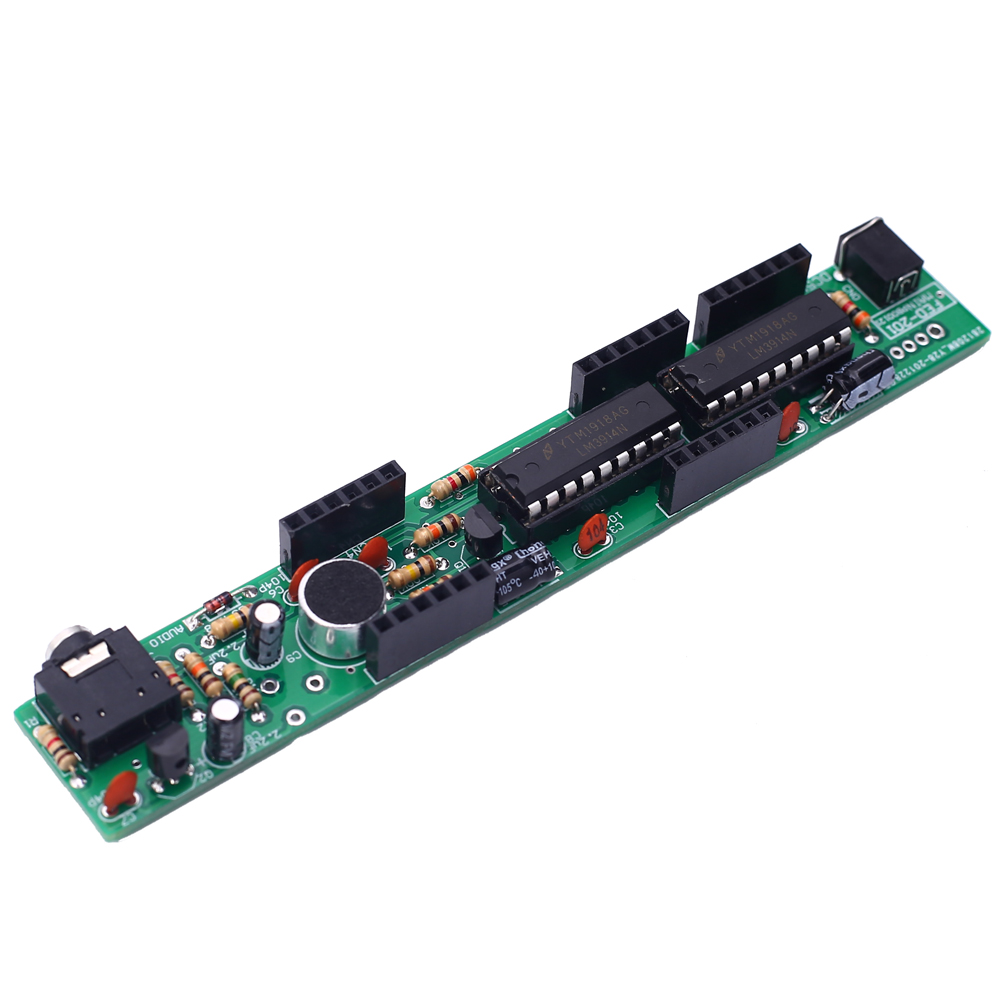
1.Introduction:
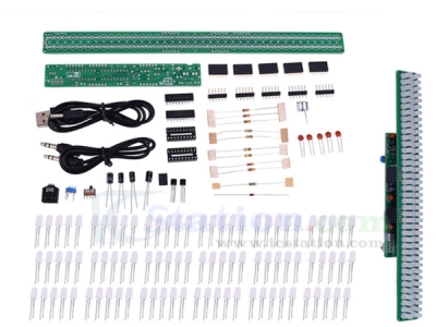
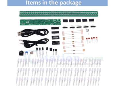
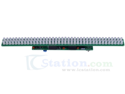
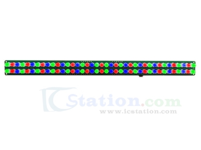
FED-202 is a Audio Spectrum Indicator DIY Kit. It can display in Red/Green/Blue according to the input audio signal from microphone.It can be used to display the intensity of audio.The number of LED displayed changes according to the intensity of the audio.
2.Feature:
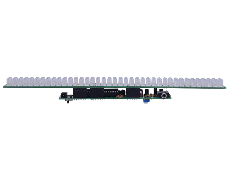
78pcs highlight LED.
Perfect simple circuit.
Automatic flashing.
Adjustable sensitivity.
3.Parameter:
1>.Product Name: FED-202 Audio Spectrum Indicator DIY Kit
2>.Product Number: FED-202
3>.Work Voltage: DC 3V-12V
4>.Work Current: 120mA
5>.Power Type: 3.5mm Power Socket
6>.Work Mode: Switch Control
7>.Color: Red+Green+Blue LED
8>.Work Temperature: -40℃~85℃
9>.Work Humidity: 5%~85%RH
10>.Size(Installed): 253x20x30mm
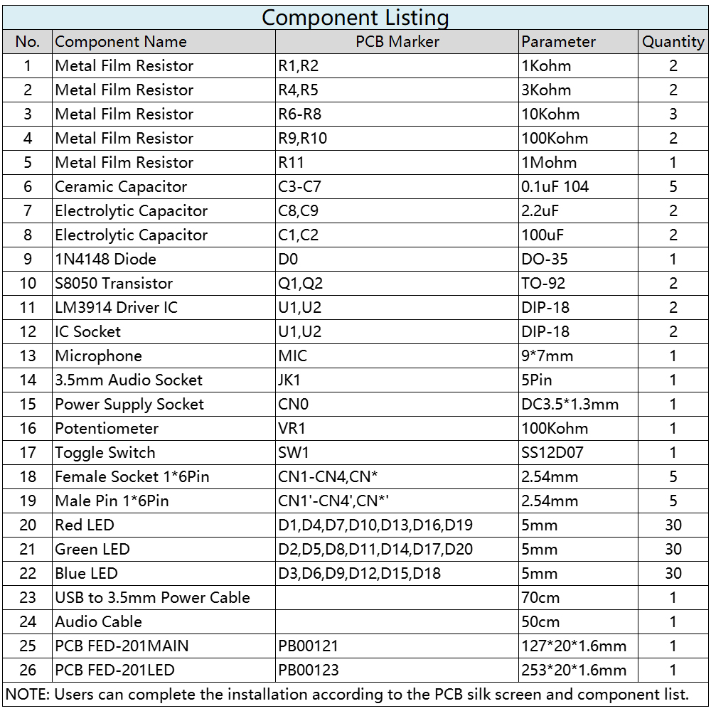
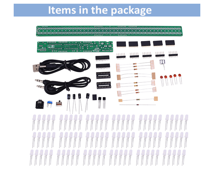
4.Installation Steps (Please download the pdf manual):
.png)
| Quantity | 3+ | 5+ | 10+ |
| Price | $6.85 | $6.70 | $6.50 |
ICStation doesn't accept any form of pay on delivery. Items used to be shipped after payment. Below are the payment methods we can accept at the moment:
1) Paypal Payment
PayPal is a secure and trusted payment processing service that allows you to shop online. PayPal can be used at icstation.com to purchase items by Credit Card (Visa, MasterCard, Discover, and American Express), Debit Card , or E-check (i.e. using your regular Bank Account).

We are PayPal Verified 
2) Bank Transfer / Wire Transfer / T/T
Bank Transfer / Wire Transfer / T/T payment methods are accepted for orders which the total price is up to US$300. The bank will charge about US$50 for the transfer fee if we do the payment in these ways. Feel free to contact us for bank payment details if you need pay via bank.
For other payment method, please contact us at orders@icstation-team.com for more details.