Your Shopping Cart Is Empty!
If you already have an account, Sign in.
If you already have an account, Sign in.


1.Description:
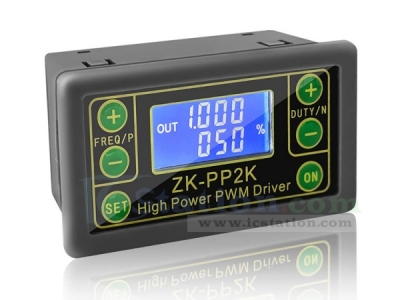
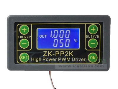
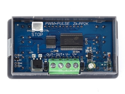
ZK-PP2K signal generator is a device that provides electrical signals at a variety of frequencies, square wave, pulse and output levels. It is used as a signal source or excitation source for testing. Widely used in production practice and technology.
Support dual mode: PWM mode and PULSE mode.
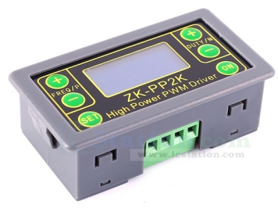
Support high current output and can be directly connected to the motor.
2.Features:
1>.Dual mode: PWM mode and PULSE mode
2>.LCD high definition display
3>.Support frequency adjustment
4>.Support duty cycle adjustment
5>.High precision detection
6>.Support power-down memory function
7>.1-Channel signal output
8>.Support reverse protection
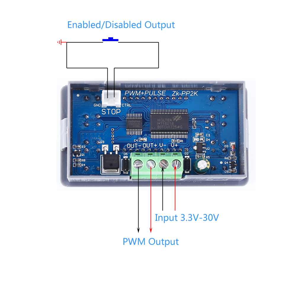
9>.Support enabled/disabled output
10>.Direct drive LED/Motor/solenoid valve
3.Parameters:
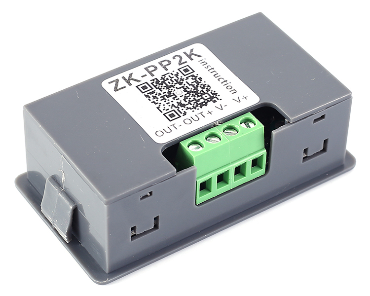
1>.Product name: ZK-PP2K PWM Signal Generator
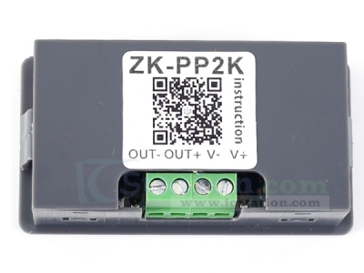
2>.Model: ZK-PP2K
3>.Work voltage:DC 3.3V-30V
4>.Frequency range:1Hz~150KHz
5>.Frequency accuracy:2%
6>.Duty cycle range:0.00%-100%
7>.Output Current:8A(Max)
8>.Number of pulses:1~9999 or Infinite
9>.Delay time:0.000s~9999s
10>.Pulse width:0.000s~9999s
11>.Time accuracy:1ms
12>.Output amplitude:Same to input voltage
13>.Work Temperature:-20℃~85℃
14>.Work Humidity:0%~95%RH
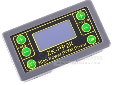
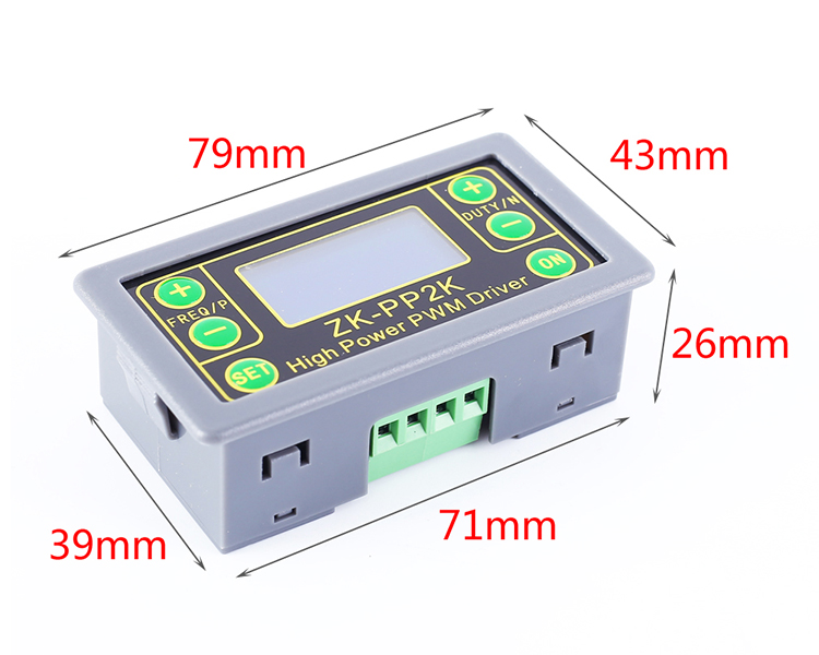
15>.Size:79x43x26mm
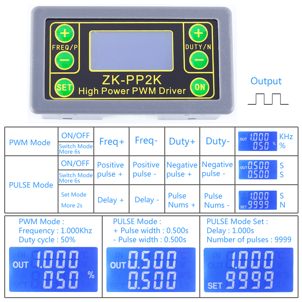
4.Work Mode:
1>.PWM Mode: Frequency, Duty cycle
1.1>.It is PWM mode when display ‘%’.
1.2>.The factory default mode is PWM mode.
1.3>.Button FREQ+ and FREQ- are used to setting output frequency.User can short press by set value in minimum unit or keep press to continuous setting. Frequency range is 1Hz to 150KHz.
1.4>.Button DUTY+ and DUTY- are used to setting output duty cycle for frequency.User can short press by set value in minimum unit or keep press to continuous setting. Duty cycle range is 0.00% to 100%.
1.5>.Short press button ‘ON’ to enabled or disabled output.It is enabled output when display symbol ‘OUT’ on left.It is disabled output if no display symbol ‘OUT’ and module will output 0V.
1.6>.The default factory frequency is 1KHz and the duty cycle is 50%.
1.7>.Switch work mode:Keep press button ‘SET’ about 6 second.Then it is enter into PULSE mode if symbol ‘%’ disappear on right.
2>.PULSE Mode:Pulse width, Delay, Pulse number
2.1>.It is PWM mode without display symbol ‘%’.
2.2>.Button P+ and P- are used to set time for positive pulse width.Displayed on the first line.Set time range is 0.000s~9999s.
2.3>.Button N+ and N- are used to set time for negative pulse width time.Displayed on the second line.Set time range is 0.000s~9999s.
2.4>.Short press button ‘ON’ to enabled or disabled output.It is enabled output when display symbol ‘OUT’ on left.It is disabled output if no display symbol ‘OUT’ and module will output 0V.
2.5>.The default factory positive pulse width is 0.5 seconds, and the negative pulse width is 0.5 seconds.
2.6>.Long press button ‘SET’ for 2 seconds to enter into set the number of pulses and delay time.Screen will display symbol ‘SET’ at lower left corner. Note:Once in this mode,the output will be disabled and output pulse will be cleared.
2.7>.Button P+ and P- are used to set delay time.Set time range is 0.000s~9999s.
2.8>.Button N+ and N- are used set the number of pulses.Set range is 1~9999 or Infinite.
2.9>.The factory default delay time is 0 seconds, and the number of pulses is infinite (display ‘----’).
2.10>.Automatic return to pulse interface by press button ‘SET’ for 2 seconds.
2.11>.Short press button ‘ON’ to after set delay time and then start output the set number of pulses.
2.12>.It will automatically output 0V if the number of pulses is sent.The output will be disabled and clear pulse numbers if press button ‘ON’ during output.
2.13>.The number of set pulses is output each time when module power on and then stop output or press button ‘ON’ to restart.
5.Practical application:
1>.PWM output 20KHz,60% : Select PWM mode.Set frequency to 20.00 and duty cycle to 060%.
2>.Output turn ON 0.6s,OFF 0.2s,infinite loop : Select PULSE mode.Set positive pulse width to 0.600 and negative pulse width to 0.200.Delay time to 0.000.Number of pulses to ‘----’.
3>.Delay 5s after power ON or press ‘ON’ button.Then output turn ON 0.6s,OFF 0.2s,infinite loop : Select PULSE mode.Set positive pulse width to 0.600 and negative pulse width to 0.200.Delay time to 5.000.Number of pulses to ‘----’.
4>.Delay 5s after power ON or press ‘ON’ button.Then output 10ms high level signal,10ms low level signal,cycle 100 times : Select PULSE mode.Set positive pulse width to 0.010 and negative pulse width to 0.010.Delay time to 5.000.Number of pulses to 0100.
5>.Delay 5s after power ON.Then keep output : Select PULSE mode.Set positive pulse width more than 0(any value) and negative pulse width to 0.000.Delay time to 10.00.Number of pulses to ‘----’.
6.Use steps:
1>.Connect to power supply.
2>.Select work mode as following manual.
3>.Short or long press button ‘FREQ+’ or ‘FREQ-’ to set parameter.
4>.Short or long press button ‘DUTY+’ or ‘DUTY-’ to set parameter.
5>.Connect to load.
7.Application:
1>.Square wave signal generator, generating square wave signal for experimental development
2>.Used to generate a square wave signal that controls the motor driver
3>.Generate adjustable pulses for use by the MCU
4>.Dimmer
5>.Speed governor
8.Note:
1>.It’s 1-channel signal output signals.
2>.Its maximum output current is 8A.Therefore it can directly drive high-power devices such motor.
3>.Please read use manual and description before use.
9.Package:
1pc ZK-PP2K PWM Signal Generator
| Quantity | 3+ | 5+ | 10+ |
| Price | $6.20 | $6.00 | $5.85 |
ICStation doesn't accept any form of pay on delivery. Items used to be shipped after payment. Below are the payment methods we can accept at the moment:
1) Paypal Payment
PayPal is a secure and trusted payment processing service that allows you to shop online. PayPal can be used at icstation.com to purchase items by Credit Card (Visa, MasterCard, Discover, and American Express), Debit Card , or E-check (i.e. using your regular Bank Account).

We are PayPal Verified 
2) Bank Transfer / Wire Transfer / T/T
Bank Transfer / Wire Transfer / T/T payment methods are accepted for orders which the total price is up to US$300. The bank will charge about US$50 for the transfer fee if we do the payment in these ways. Feel free to contact us for bank payment details if you need pay via bank.
For other payment method, please contact us at orders@icstation-team.com for more details.